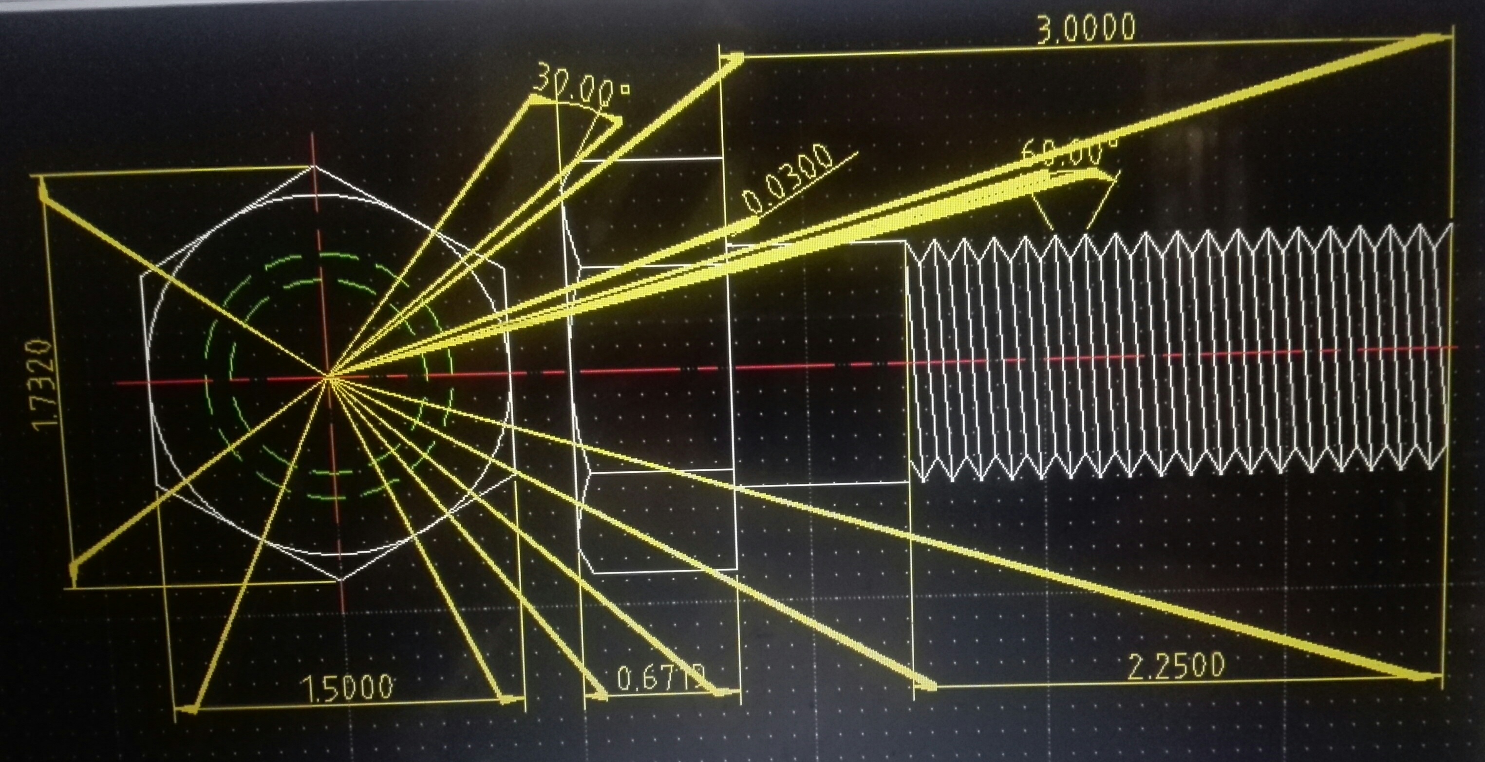

It allows to draw entities with different features from the others of the same layer, select color, width, line type all this before creating entities, after set new preferences the further entities will have the new features. Moreover, clicking with right mouse button, you can select if defreeze or freeze layer, add or remove a layer, edit a layer or toggle its visualisation. This print or not the entities relative to the layer

Considering the list here below there are other proprieties This icon add a layer this icon remove a layer with this icon is possible to set the layer's name, color, width, and line type. More in detail this section: this icon shows all the layers in the work and As shown in the picture there is the layer 0 always present as default. Layers are useful to visualize only certain entities, or put together entities with similar proprieties, depending on preferences, needs, kind of work planning.
#Librecad move to layer manual#
Finally, to draw a line from violet point to the green point having the origin is blue point, the coordinates are: first point (violet) 1.5,2.5 – second point (green) 3.5,5.5 LibreCad User manual – page 3 Now, if want to draw a line from the violet point to the green point, we need to enter other coordinates of the violet point, because now it does not lays on the origin, the origin is -1,5,-2,5, so the difference between the violet and blue point is 1.5,2.5. Then to draw a line from this new origin to the green point, the first coordinates are 0,0 and the second coordinates are 3.5,5.5. In case1 too is used this method, but the operation results simplier because the numbers 0 simplify the operation.

Now the distance between the blue point and the green point is given by the algebraic differences between the coordinates of the green point and the coordinates of the blue point, so the distance is 3.5,5.5. We pretend the origin switch to the blue point. In this case the origin does not lays on 0,0 but in another point. The coordinates are: first point (violet) 0,0 – second point (green) 2,3. The distance of the green point from origin is 2 on the X axis is and 3 on the Y axis, so to draw a line from the violet point (that lays on the origin) to the green point we need to consider the coordinates of the violet point 0,0 and the green point is 2,3. Relative coordinates (the origin does not lay in coordinates 0,0) To simplify those concepts, let's suppose that want to locate the green point in figure 1. Absolute coordinates (the origin lays on the coordinates 0,0) 2. In LibreCad Cartesian coordinates can be inserted considering two cases, that may give the same result: 1. The coordinates can also be defined as the positions of the perpendicular projections of the point onto the two axes, expressed as signed distances from the origin, the picture explains those concepts. Each reference line is called a coordinate axis or just axis of the system, and the point where they meet is its origin, usually at ordered pair (0,0). A Cartesian coordinate system it is a system that specifies each point uniquely in a plane by a pair of numerical coordinates (1), which are the signed distances from the point to two fixed orthogonal directed lines, measured in the same unit of length. If you are already into others cad system probably this little chapter is not necessary to be read. Show the grid Turn on/off the draft mode Redraw the work Zoom in Zoom out Auto zoom Previous view Zoom a selected window Activate the pan.ĬOORDINATES Before to start with the cad commands, it is really important to have clear the meaning of the word “coordinate”. This bar is a bit more specific it allows to:

This is another common bar that many other programs have, there is nothing specific considering the “cad side”, the icons' function are in order: (*) (Please notice that LibreCad operates with. This bar is the basic bar that you may find in any other applications, is quite standard, looking at the picture under the title there are in order : LibreCad User manual (version 2.0.0 beta 1)


 0 kommentar(er)
